Normally, when people are looking to build a PC, the CPU and graphics card are the first components that get all the attention. But the motherboard also plays a very important role in the performance, overclocking potential, and expandability of the system.
Well, there are other important parts as well, such as memory, storage, the PSU, and more, but in this article, we will focus on motherboards. Actually, it’s even more specific than that. We will be discussing motherboard VRM and its importance.
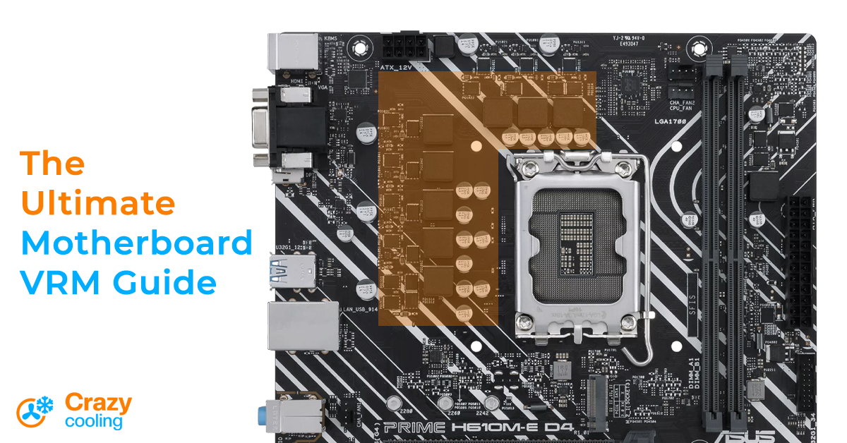
VRM is one of the factors that determine the quality of the motherboard (mobo). The word “VRM” is something you may have heard PC enthusiasts use a lot when talking about motherboards and overclocking. A good motherboard VRM with a proper cooling solution is essential if you are overclocking your CPU.
But what exactly is it, and what do you need to know about it to make the right buying decision? I’ll try to explain everything you need to know about the VRM, such as what it is, how it works, what are the “phases” in the VRM motherboard, why the VRM is important for gaming, whether the VRM requires cooling, and so on.
Motherboard VRM Guide
What is VRM on a motherboard?
VRM stands for Voltage Regulator Module. It is a part of the motherboard that, as its name suggests, regulates the voltage for PC components such as the CPU and RAM.
But what does it mean by “regulating voltage”? Let me explain in detail.
In order to power the computer, you may remember that you first need to connect the power cord to an electrical outlet from which the computer receives alternating current (AC) of either 110–127 volts or 220–240 volts, depending on what country you live in. A PSU, short for a power supply unit, is a device that takes the AC current, converts it into direct current (DC), and distributes the current to all the components of the computer.
The distributing DC current from the PSU has either 3.3V, 5V, or 12V, depending on what component it is supplying. For the CPU (and GPU), the PSU outputs 12V. But the CPU only needs 1.0–1.5V, so we need to step down the 12V as well. This is where the motherboard VRM comes in.
The VRM is responsible for stepping down that 12V DC to an appropriate DC voltage for the CPU, which is typically around 1.2V, and that DC output needs to be clean, meaning steady voltage without any fluctuations. So, this is what it means when we say regulating voltage for the CPU.
How does a VRM work?
VRM is not a single component but rather a combination of different components that work together to achieve a clean, usable voltage for the CPU. I should mention that motherboard VRM also supplies power to other PC components such as memory, but since supplying enough clean power to the CPU is more challenging, we will just consider the CPU for the majority of this article.
So to achieve a lower voltage, VRM uses a buck converter. What is a buck converter? A buck converter is a DC-to-DC power converter that steps down the voltage from its input to its output, in this case from 12V to, say, 1.2V.
The major components used for a circuit of the buck converter are MOSFET, choke, capacitor, and diode. These are very common electronic components found in almost all electronic circuits.
Worry not if you’re not familiar with them, because I will be explaining what they do in order for the VRM to output a steady, usable voltage — in as simple a way as I can. However, I won’t go into great detail about how each component actually works, as that would be a whole other topic, and we will be digging up some advanced electrical engineering stuff.
The basic circuit of a VRM is shown below, which consists of two MOSFETs, a choke, a diode, and a capacitor. Hold on as I explain what each component contributes to this circuit.
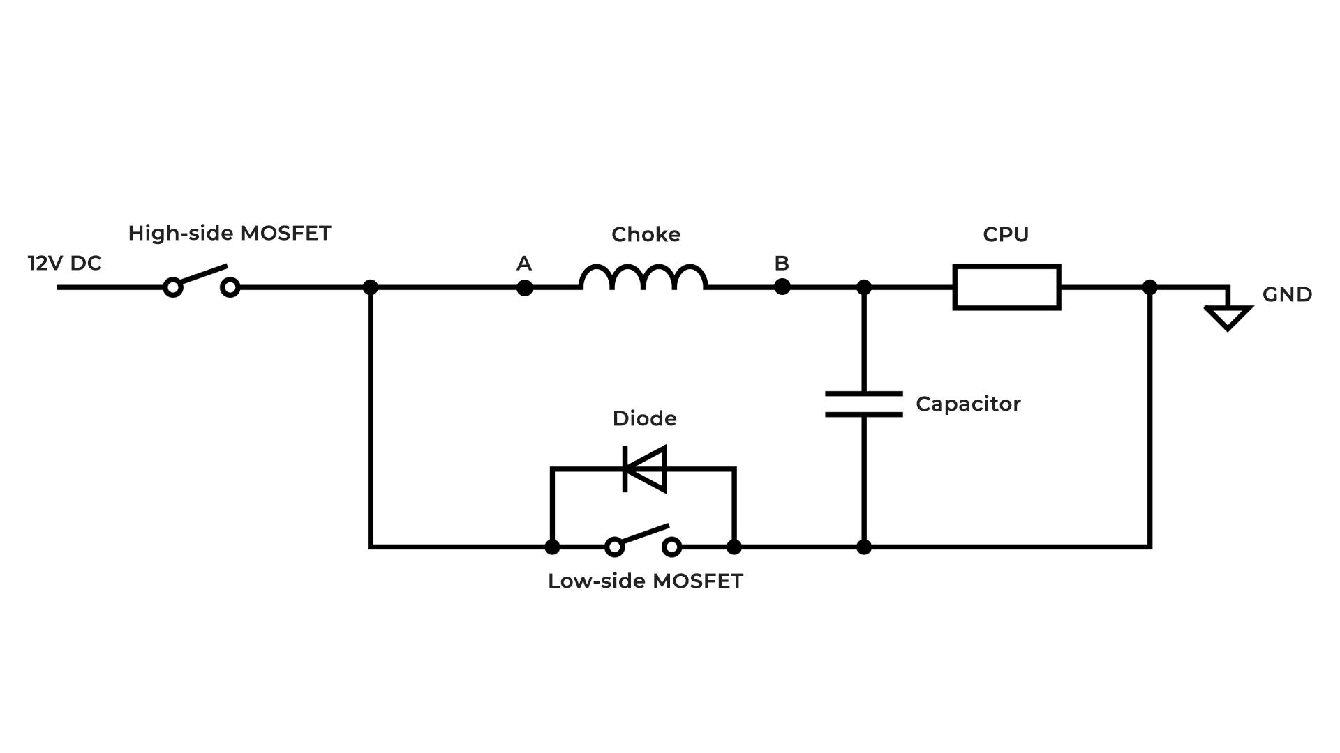
The first component we come across is the MOSFET. The MOSFET stands for a metal-oxide-semiconductor field-effect transistor. Don’t get intimidated by its long name; it is basically a type of field-effect transistor that acts as a switch. That’s why, for the sake of simplicity, I drew a symbol of a switch above instead of an actual symbol of the MOSFET.
This MOSFET is called the “high-side” MOSFET. The reason we call it high-side MOSFET is because the VRM circuit requires two MOSFETs and this MOSFET switches the high voltage – the 12V.
The MOSFET first receives the 12V DC. When the switch is closed (i.e., when MOSFET is ON), the 12V current is passed through the choke. Now, a choke is a type of inductor that is used for filtering purposes. Therefore, you may see me refer to a choke as an inductor throughout this article (though keep in mind that not all inductors are chokes).
So, what the choke (inductor) does is that it does not output the full voltage right away.
It gradually increases the voltage as long as the power is supplied to it till it’s not fully charged up (generating a magnetic field).
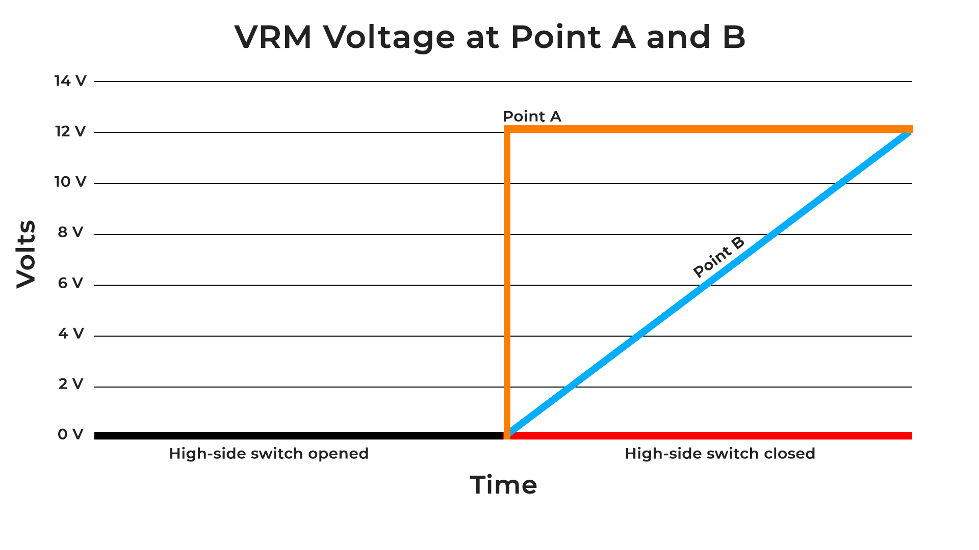
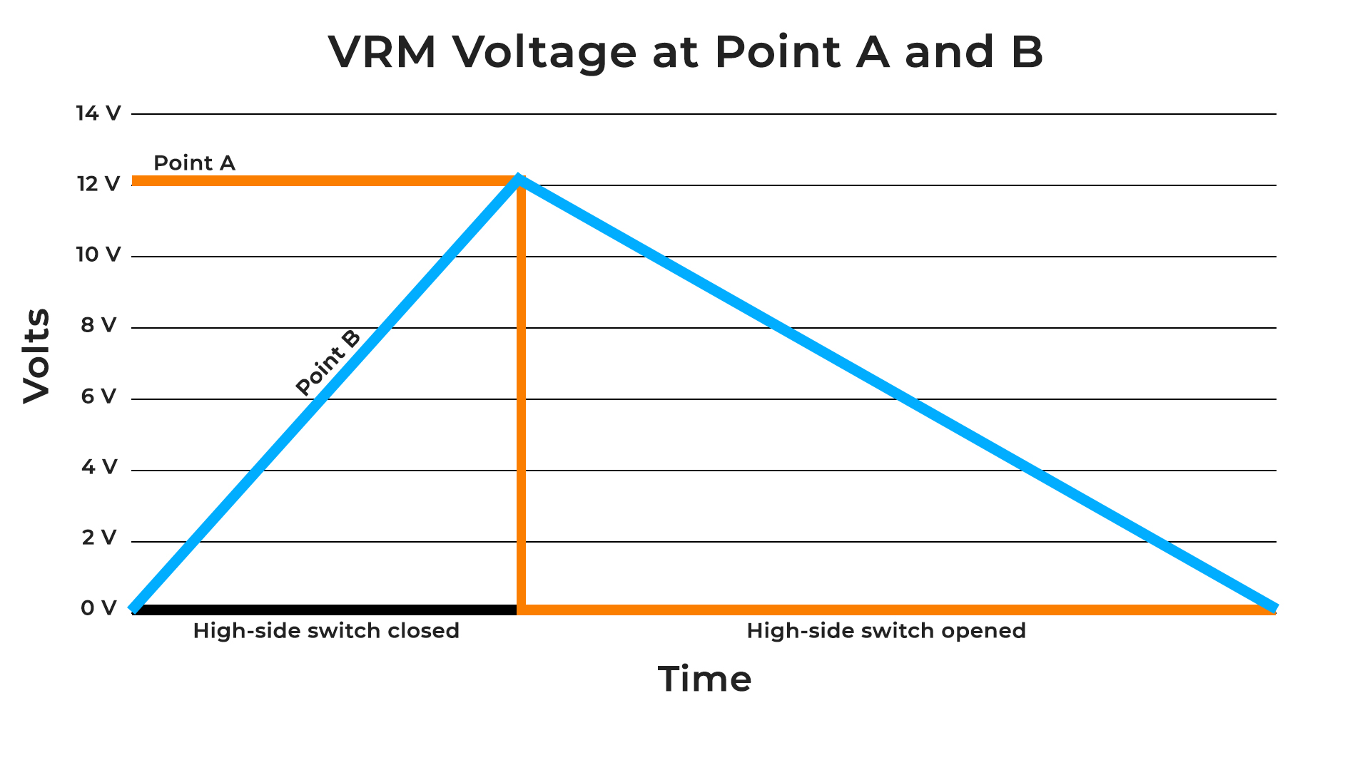
Let me explain what I mean. In the above diagram, you can see I have labeled the input of the choke as point “A” and the output of the choke as point “B.” Now, when the switch is closed, point A immediately gets 12V DC. But the same does not happen at point B because of the properties of an inductor.
An inductor changes electrical energy into magnetic energy and stores it. So, when the current flows through the inductor, it resists change in current and induces a magnetic field around it — we call it charging — which causes the voltage to drop across the inductor. The voltage drop gets smaller as the inductor charges up, causing the output voltage to gradually increase till it reaches the input voltage.
You can see the diagram and graph below how the voltage at point B increases when point A is supplied with 12V for a sufficient amount of time.
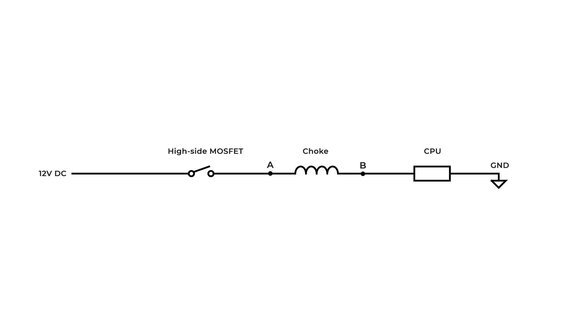
So, now you understand that as power is supplied to the inductor it steadily raises its output voltage till it reaches the input voltage. But we do not want the output voltage (point B) to reach the input voltage (point A, 12V) because that will destroy the CPU.
Therefore, once the desired voltage level for the CPU (say, 1.2V) is reached at point B, the input power to the inductor is cut off by opening the switch (turning OFF the high-side MOSFET).
This is done to prevent the voltage from rising further. However, due to the inductor’s characteristics, this now poses a new problem. When the current was flowing through the inductor, it was generating a magnetic field. But after opening the high-side switch, the voltage at point A drops to 0V, causing the magnetic field of the inductor to collapse.
Collapsing magnetic field pushes the current to point B, while point A starts to behave like the ground (GND). So, the current from the inductor wants to flow from point B to point A. But remember that currently the circuit only consists of a high-side MOSFET, an inductor, and a CPU, as seen in the second picture.
So there is no path for the current to flow from point B to point A. This will induce a sudden voltage spike seen across the CPU, which will destroy it. This voltage spike is known as flyback voltage. To eliminate flyback voltage, a reverse-biased diode is placed across the inductive load. Since the diode only allows the current to flow in one direction, it will let the current flow from point B to point A but not the other way around.
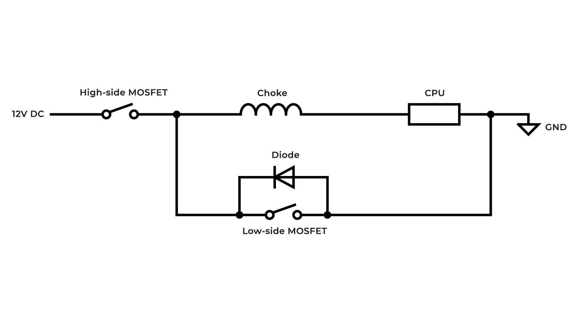
But this is still not enough. The reason is that diodes are very inefficient and can quickly become extremely hot, shortening the lifespan of them and other components around them. To avoid it, an additional MOSFET is placed as a switch parallel to the diode so that the current can flow through it for better efficiency.
The second MOSFET is called the low-side MOSFET (low-side switch). The low-side switch is closed as soon as possible when the high-side switch is opened.
You might be wondering why we can’t simply omit the diode and utilize the low-side MOSFET. That’s because even though the MOSFETs can work at 300KHz, switching 300,000 times per second, it is still not fast enough to eliminate the voltage spike.
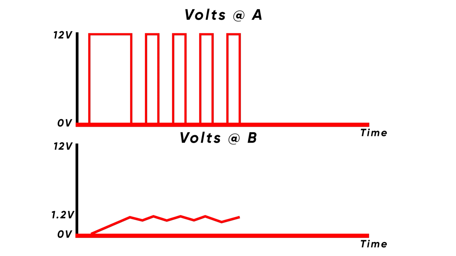
Only now, the voltage at point B feeding the CPU will not increase, instead, the inductor starts to discharge and the voltage starts to slowly decrease.
But we don’t want the voltage to drop to zero. We want constant voltage at point B, as required by the CPU. For that, we need to raise the voltage again just after a slight voltage drop. That is done by repeating the earlier process – closing the high-side switch and opening the low-side switch until the voltage hits the required volts.
Repeatedly switching the MOSFETs will deliver a relatively steady voltage to the CPU. The faster the MOSFETs switch, the more stable the output voltage becomes. Below is the graph of the voltage at points A and B when the two MOSFETs are repeatedly switched to get around 1.2V DC.
Now you know what MOSFET, choke (inductor), and diode does in a VRM circuit. There is also the capacitor, which is connected across the CPU, as shown in the first diagram.
This is done to minimize the voltage spikes, delivering smoother output voltage.
PWM Controller
So now you know how all the components in the VRM circuit work to achieve a fairly constant voltage. But there is still one very important thing I have not mentioned yet.
I previously described how stepping down the 12V DC to a desired lower voltage is accomplished by turning on and off the MOSFETs of the VRM section. To achieve the desired output voltage, MOSFETs need to be switched at a certain frequency and at a certain pulse width. This method is known as pulse-width modulation, or PWM for short.
What is a PWM controller and why is it important for VRM? A PWM controller is a microcontroller responsible for sending pulses to MOSFETs at a certain frequency and at a certain pulse width. PWM controller is needed to precisely switch MOSFETs to achieve the desired voltage.
What are the Phases in VRM?
I hope the above explanation makes it apparent that adding a capacitor and switching MOSFETs as quickly as possible can smooth out the output voltage. However, even after that, there will still be some voltage spikes in the output voltage, which is bad for the stability of the CPU.
The other solution to further smooth out the voltage is to add more of these circuits in parallel with each other. A VRM having one circuit, as explained above, is called a single-phase VRM, while a VRM having multiple such circuits is called a multi-phase VRM.
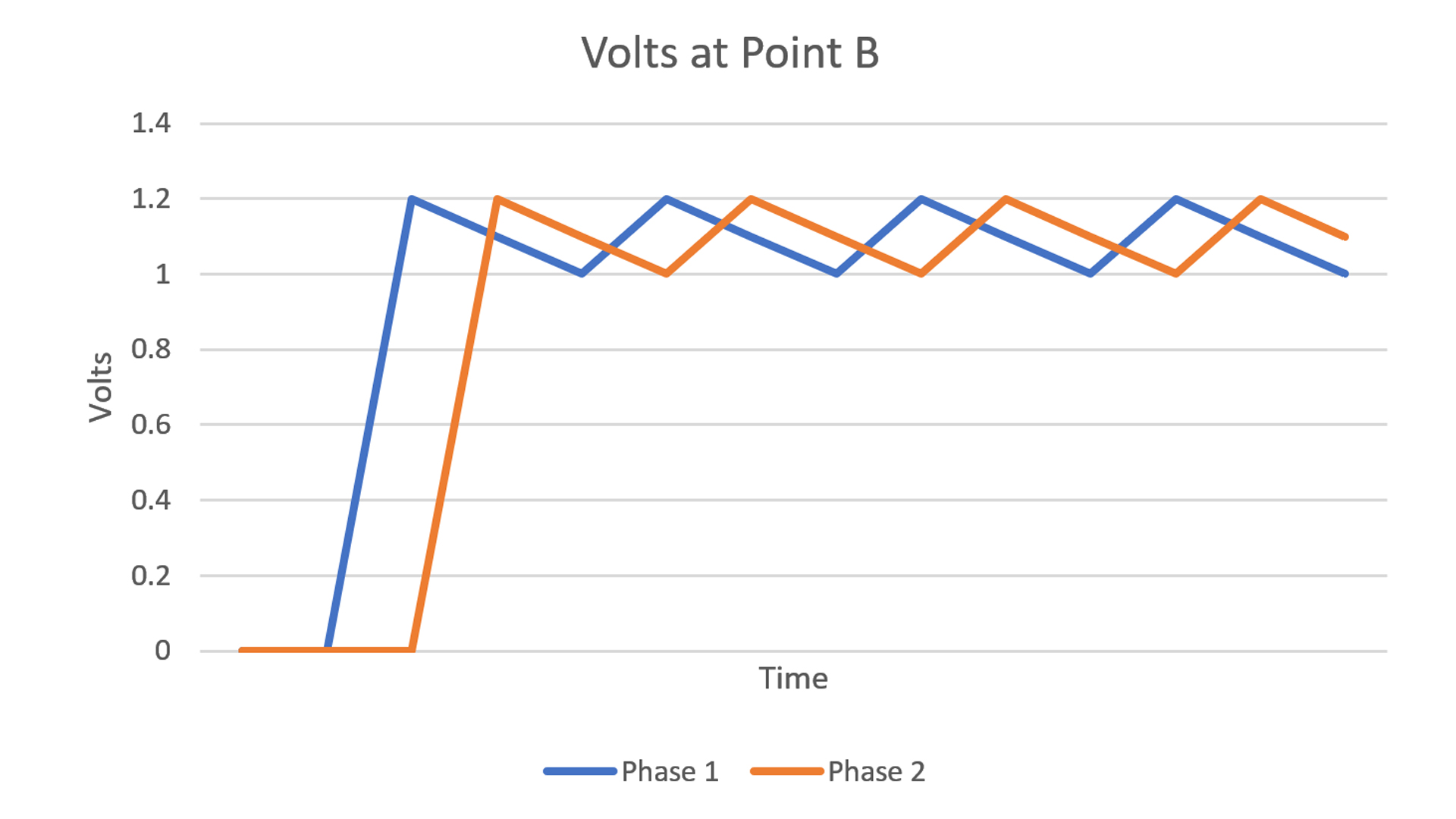
For example, if we add an additional VRM circuit in parallel to the existing one, we call it a two-phase VRM. The MOSFETs of one circuit are switched just after the other, so when the inductor of one phase is discharging, the other is charging — making two voltages out-of-phase.
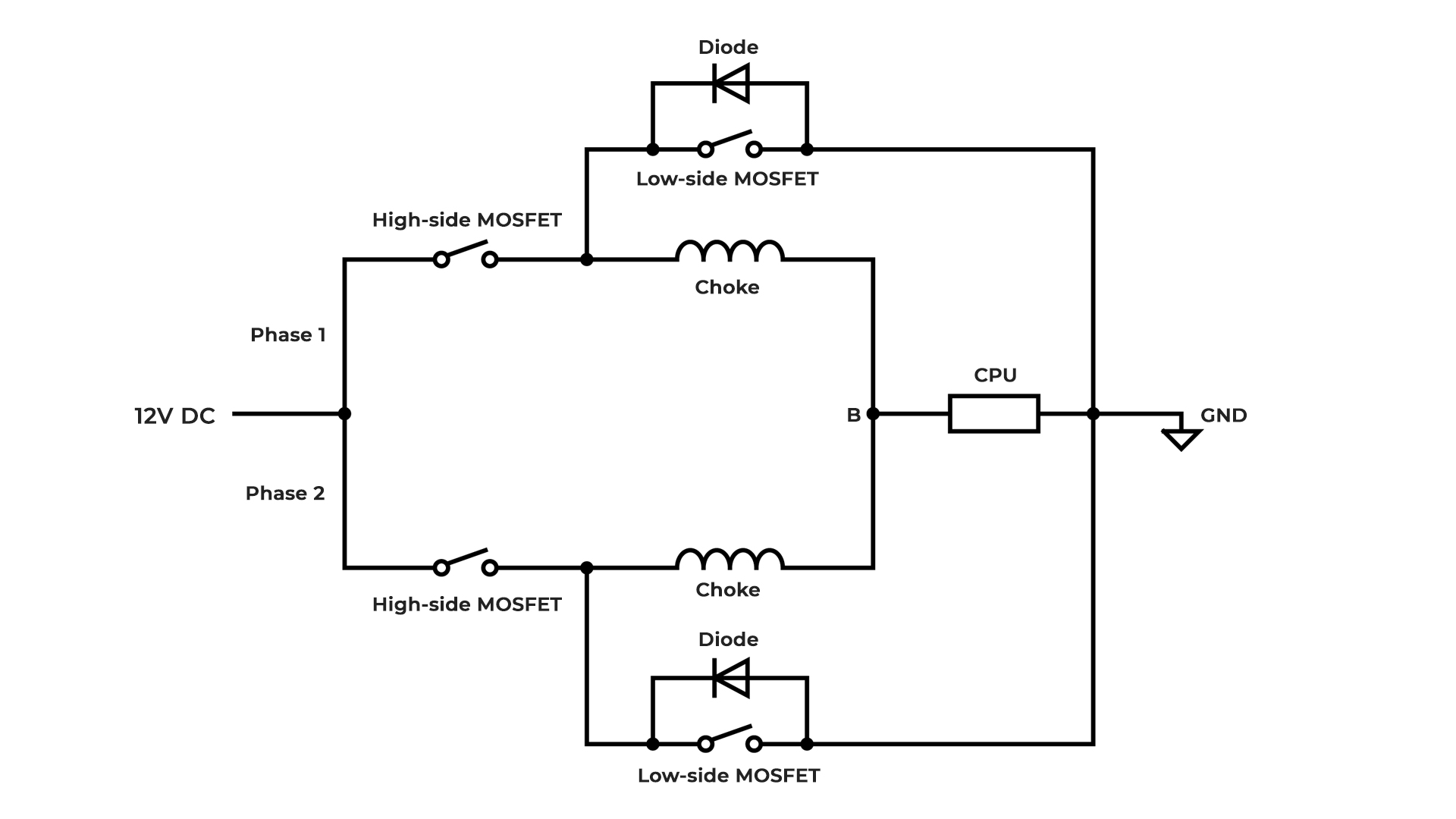
This implies that when the first inductor’s output voltage dips during its discharging process, the second charging inductor takes over and raises the output voltage [see the graph below]. Again, the first inductor starts charging and takes control when the other one is discharging. Repeating this process will make the voltage more stable.
The graph of the output voltage shown below should help you understand it more easily. The two differently colored graphs represent two voltages of two phases.
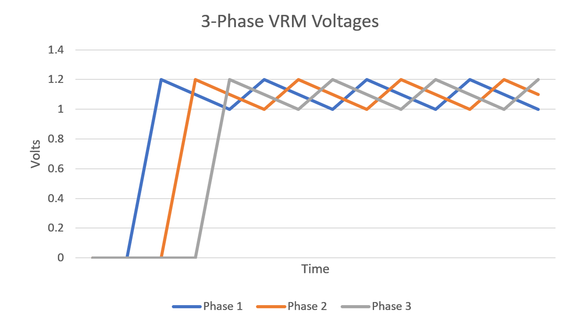
Likewise, increasing the number of parallel circuits in a VRM will produce an even cleaner voltage. The graph below depicts how four phases help smooth the output voltage. The voltage is more stable the more VRM circuits and phases there are.
The stable output voltage is not the only advantage of the multi-phase VRM. It also reduces the load on each component because the current needed for the CPU is also divided into each circuit. So, the more phases, the less load on each component.
For instance, in two-phase VRM, only half the current required by the CPU goes through each circuit, lessening the stress on each component of both circuits. If it’s a four-phase VRM, only 25% of the total current required by the CPU go through each phase.
To illustrate, if there is a two-phase VRM and a CPU requires 80 ampere (amp) current, then the required current is split into two circuits, requiring only 40 amps on average to go through each phase. If it’s a four-phase VRM, only 20 amps on average go through each phase.
Therefore, in a multi-phase VRM design, manufacturers can use cheaper, lower-rated components.
So in conclusion, the more phases a VRM has, the more stable the voltage becomes while also putting less load on components, which is good for reducing the operating temperature and increasing the longevity of the components. Therefore, the more expensive motherboards tend to have more phases.
What are Phase Doublers in VRM?
A phase doubler basically doubles the number of phases, but from the same PWM signal. A doubler will split the frequency of the PWM signal to make it two phases.
This means that the doubler can take the pulses from the 4-phase PWM controller and make 8-phase VRM. This 8-phase VRM using doublers is better than the regular 4-phase VRM as the load is distributed into eight phases, resulting in a lower VRM temp.
However, it is not as efficient as the true 8-phase VRM. A doubler will cut the frequency of the PWM signal in half in each phase, and therefore there is a delay that will impact the performance of the VRM.
When you see a motherboard with 8, 10, 12, 14, or 16 VRM phases, it’s likely the manufacturer has used doublers to achieve that.
A doubler will drive two VRM circuits, so there will be two high-side MOSFETs, two low-side MOSFETs, and two chokes.
Does VRM need cooling?
Yes, VRMs need cooling. MOSFETs in a VRM switch hundreds of thousands of times each second to stabilize the output voltage, which generates a lot of heat, especially when the processing unit is under sustained load.
And if your processing unit is under sustained load or you’re overclocking the CPU, then the power requirement is very high, which causes the VRM to produce even more heat, to the point where it may damage other components around it.
To prevent from that happening, motherboards come with a heatsink over MOSFETs to cool down the VRM temp. Therefore, the best motherboards come with the best VRM cooling system with a beefy heatsink. Some high-end motherboards may even feature active cooling using a fan.
How to read VRM phases?
Typically, you will find a motherboard showing VRM phases in the form of two numbers separated by a “+” sign in its specifications sheet, such as 4+1, 4+2, 6+2, or 8+2.
The phase count for the CPU is represented by the number before the plus (+) symbol, while the number after it represents the phase count for the memory.
For example, 6+2 indicates six phases for the CPU and two for the memory.
Motherboard manufacturers also love to use words like Power Phases, Power Stages, and Power Phase Design when referring to VRM phases. For example, you may find Asus using “Power Stages” to indicate a motherboard VRM count. So, when you see those words, know that they mean VRM phases.
How do you calculate VRM phases?
The simplest way to find a motherboard’s number of VRM phases is to look at the specs sheet. However, sometimes manufacturers don’t include motherboard VRM phase information in their specs sheet. Or, there are times when they have lied about VRM phase counts.
In those cases, you need to manually check the VRM count. The most common and simplest way to do that is to count the number of chokes. However, as easy as this method is, it’s not always reliable because counting chokes alone does not always tell the whole truth. Manufacturers may have used phase doublers.
And even when not using phase doublers, in the past, motherboard manufacturers have tried to make the board appear to have a higher phase count than it actually has by putting multiple chokes in a single phase.
So, one of the ways to accurately know the VRM phase count is to use a digital multimeter and basically figure out the circuit of the VRM. Buildzoid from Actually Hardcore Overclocking has made a YouTube video showing how to do that.
Motherboard VRM in a Nutshell
VRM, which stands for Voltage Regulator Module, is like a mini power supply for computer components such as CPU, GPU, and memory. It takes the 12V DC from the power supply unit (PSU) and steps it down to a usable voltage for the CPU, which is typically around 1.2V.
A VRM circuit consists of electronic components, including two MOSFETs (high-side and low-side), a choke, a diode, and a capacitor. They all work together to produce a clean, stable, and usable voltage for the CPU (and other components).
Among the other components, MOSFETs, which act as switches, get the hottest as they switch hundreds of thousands of times a second. Therefore, it requires a good cooling system with a heatsink; otherwise, the VRM might not function efficiently, which would lead to suboptimal computer performance.
To make the output voltage more stable, a multi-phase VRM is used. A multi-phase VRM uses multiple VRM circuits driven by a multi-phase PWM controller to make the output voltage more stable and to put less burden on each components.
Manufacturers may also use phase doublers to double the phase count. Phase doublers are components that manufacturers use to double the number of phases that a PWM controller is capable of handling. Although it is less expensive than true-phase VRM because it needs fewer PWM controllers, it is less effective.
So, in conclusion, VRM is a crucial part in a motherboard. A good motherboard VRM is essential for good performance not only for gamers and overclockers, but for everyone.
FAQs about VRM Motherboard
Are more VRM phases better?
The quality of the components and other factors also play a role, but generally, yes, the more motherboard VRM phases, the better the stability of the output voltage for the CPU.
Is VRM important in motherboards?
Yes, VRM is very important in motherboards. The CPU and RAM will not be able to get the stable voltage required without a VRM.
Does VRM matter for gaming?
Yes, VRM does matter for gaming. A bad VRM might not be able to supply the CPU with enough power during gaming, which could lead to poor gaming performance. A VRM with proper cooling is thus necessary for good gaming performance.
Does VRM affect PC performance?
Yes, VRM does affect performance. The CPU requires enough power with clean voltage for good PC performance, which is supplied by the VRM. If VRM is not able to supply that clean, stable voltage to the CPU, performance will suffer.
What are the limitations of bad VRM?
A bad VRM will overheat and degrade the performance and components of the PC. Even when the CPU is capable, the computer might not be able to function well under load because of a poor VRM. You may also experience unexpected shutdowns. A bad VRM will also limit you from overclocking your CPU.
How to choose a good VRM?
Consider a motherboard with a good number of VRM phases, a proper cooling solution, and quality VRM components, such as solid-state capacitors over liquid-based electrolytic capacitors. It’s best to watch or read reviews of the motherboards before buying one.